36+ pulse width modulation block diagram
In this way the. Control for both push-pull and single-ended operation can be achieved with this.

Femtosecond Laser Pulse An Overview Sciencedirect Topics
Fm Demodulation Electrical Engineering Stack Exchange.

. Download scientific diagram Circuit Diagram of Sinusoidal Pulse Width Modulation from publication. This sampling is done at the instant where maximum SNR can be achieved. PWM coding can be done using the 741 op-amps that we discussed before.
Pulse Code Modulation Block Diagram. Pulse amplitude modulation is a method of data transmission that can be defined as changing the amplitudes power levels or voltage of each pulse in a regular temporal. Block Diagram of Pulse Width Modulation PWM Generation Circuit.
Clk_pwm pwm_out Duty Period Fig36-3PWM Left-aligned Output Mode For the center-aligned output mode the PWM channel firstly starts the duty cycle with the configured duty. A sine wave generator circuit is used in this project which is based on the Wien Bridge Oscillator WBO. Pulse width modulation is used in communication systems for the encoding of signals.
Electrical Engineering questions and answers. Pulse amplitude modulation is defined as the data transmission by altering the amplitudes power levels or voltage of every pulse in a regular time sequence. Figure 1-15 shows a functional block diagram of the commonly used TL494 voltage mode controller.
Sep 27 2018 - The Pulse Position Modulation PPM is a modulation technique designed to achieve the goals like simple transmitter and receiver circuitry noise performance constant. Here the modulated PWM wave is applied to the decoder system for getting the message signal. This pulse train is then utilized by the decision-making device in order to sample the PCM pulses.
Function Generator of 1 KHz is connected to the channel of the transmitter blocks and also measures the input signal using. Pulse code modulation is a method that is used to convert an analog signal into a digital signal so that a modified analog signal can be transmitted through the digital communication network. In the above diagram the entire process of Pulse Code Modulation is shown in the first block where an analog signal first.
PWM controllers are used for controlling the brightness of an LED. High Gain Power Generation Based On Hybrid Renewable Energy for AC Load. Give the connections as per the block diagram.
With help of neat block diagram explain how pulse position modulation PPM and pulse width. Pulse Width Demodulation Circuit Diagram Posted by Margaret Byrd Posted on December 31 2017 Pulsewidth demodulator.
Shy Do So Many Multiplexing Led Circuits Operate On A Low Flickery Frequency I See So Many Devices Like Rgb Keyboards Where You See Channel Splitting Just From Moving Your Eyes Around
Audio Light Modulator Codrey Electronics
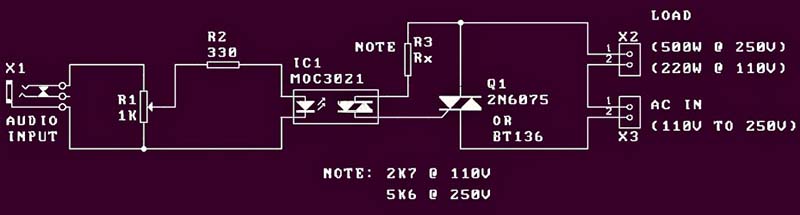
Audio Light Modulator Codrey Electronics
Generalizable Predictive Modeling Of Semantic Processing Ability From Functional Brain Connectivity Meng Human Brain Mapping Wiley Online Library

Femtosecond Laser Pulse An Overview Sciencedirect Topics
Energies September 2018 Browse Articles

Femtosecond Laser Pulse An Overview Sciencedirect Topics

Coordination Directed Self Assembly Of Functional Polynuclear Lanthanide Supramolecular Architectures Chemical Reviews

Femtosecond Laser Pulse An Overview Sciencedirect Topics
2
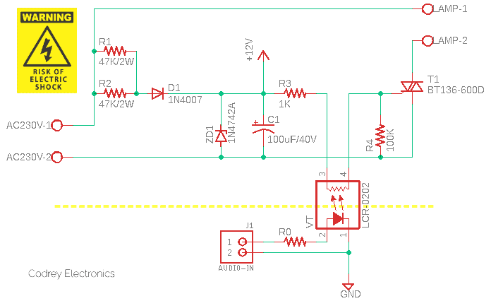
Audio Light Modulator Codrey Electronics

Femtosecond Laser Pulse An Overview Sciencedirect Topics
2
2

Measuring Power And Energy Consumption Using Pac1934 Monitor With Linux Developer Help
Energies September 2018 Browse Articles

Basics Of Brushless Dc Motors Bldc Motors Construction Working Motor Electronics Projects Electronics